Turbine flow meter for gas Energoflow EFS-T
Reference Turbine Gas Meters EFS-T
Overview
TABLE -1
| DN | Standard size | Qmax, m 3 /h | Qmin, m 3 /h |
|---|---|---|---|
| 400 | G6500 | 10000 | 500 |
| 400 | G4000 | 6500 | 325 |
| 300 | G4000 | 6500 | 325 |
| 250 | G2500 | 4000 | 200 |
| 200 | G1600 | 2500 | 125 |
| 150 | G1000 | 1600 | 80 |
| 100 | G400 | 650 | 35 |
| 80 | G250 | 400 | 20 |
| 50 | G100 | 160 | 8 |
TABLE - 2
| Parameters | Value | |
|---|---|---|
| General industrial application design | Explosion-proof design | |
| Measuring medium | air | |
| Operating pressure, MPa | 1,6; 4,0; 6,3 | |
| Limits of basic relative permissible error, not worse % |
± 0,2 | |
| Repetition, at least % | ± 0,03 | |
| Repeating accuracy within 2 years, at least % | ± 0,1 | |
| Frequency output with adjusted multiplication factor Fmax, kHz | 5 | |
| Signal of flow rate excess for the emergency system shutdown | Type «dry contact» | |
| Loading capacitance of emergency output shutdown: voltage, V, max max current, mA, max |
24 20 |
|
| Operating conditions: -Temperature of operating environment and ambient air, °C, at least - Relative humidity of air at temperature +25 °C, % - atmospheric pressure, kPa |
10 up to 30 up to 80 from 84,0 up to 106,7 |
|
| Power consumption, W, max | 0,5 | 6,0 |
| Supply voltage, DCV | from 9 up to 24 | |
| Lifetime, min. years | 10 | |
- hourly- for every preceding hour - size of archive 1488 records (62 days);
- daily- for every preceding day - size of archive 730 records;
- power on/off instances - size of archive 512 messages;
- emergency situations - size of archive 720 messages;
- intervention - changing the adjustment parameters (size of archive 889 messages).
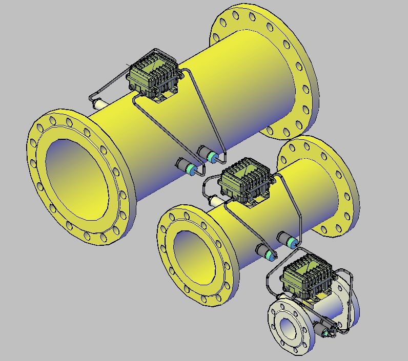
APPENDIX A - General Appearance
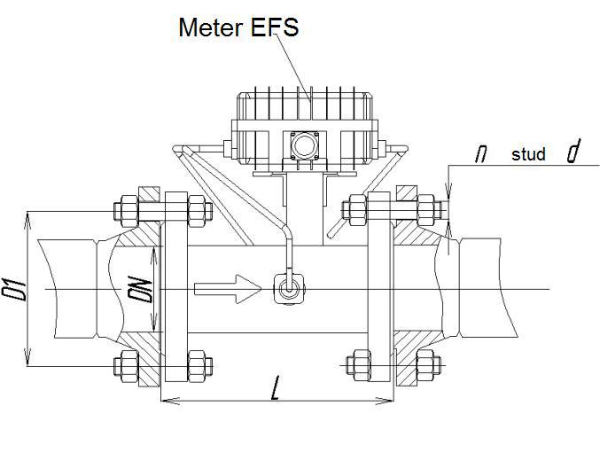
APPENDIX B - Possible solutions of meter mounting
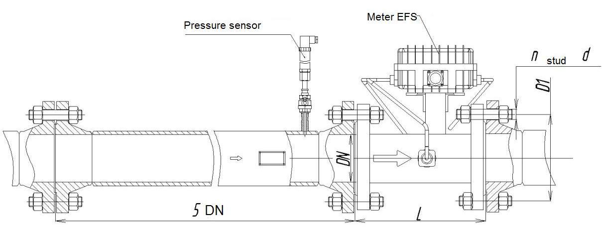

APPENDIX C -Dimensions of the meter with straight run

TABLE - 3
| DN, mm | Rating, MPa | L, mm | D1, mm | n | d, mm |
|---|---|---|---|---|---|
50 |
1,6 | 150 |
125 | 4 |
18 |
| 4,0 | 125 | 16 | |||
| 6,3 | 135 | 22 | |||
80 |
1,6 | 240 |
-- | 8 |
18 |
| 4,0 | 160 | 16 | |||
| 6,3 | 170 | 22 | |||
100 |
1,6 |
300 |
180 | 8 |
22 |
| 4,0 | 190 |
20 | |||
| 6,3 |
200 | 26 | |||
150 |
1,6 | 450 |
240 | 8 |
22 |
| 4,0 | 250 | 24 | |||
| 6,3 |
280 | 33 | |||
200 |
1,6 | 600 |
295 | 12 |
22 |
| 4,0 | 320 | 27 | |||
| 6,3 | 345 | 33 | |||
250 |
1,6 | 750 |
355 | 12 |
26 |
| 4,0 | 385 | 30 | |||
| 6,3 | 400 | 39 | |||
300 |
1,6 | 900 |
410 | 12 | 26 |
| 4,0 | 450 | 16 |
30 | ||
| 6,3 | 460 | 39 | |||
400 |
1,6 | 1200 |
580 | 16 |
30 |
| 4,0 | 670 | 42 | |||
| 6,3 | 715 | 48 |
APPENDIX D - Order code for reference turbine
gas meter
gas meter
TABLE - 4
| # | 1 | 2 | 3 | 4 | 5 | 6 | 7 | 8 | 9 | 10 | 11 | 12 | 13 |
|---|---|---|---|---|---|---|---|---|---|---|---|---|---|
| EFS- | T | D | G | N | P | Ak | Sm | Mp | I | Dp | Dt | S |
Legend explanation of typical order codes is given in Table 4
| # | Elements Legend | Meter's characteristics |
|---|---|---|
| 1 | EFS- | Type of the reference meter. |
| 2 | Т | Type of meter sections: Т - turbine |
| 3 | D | Nominal meter diameter, mm |
| 4 | G | Meter standard size |
| 5 | N | Flow range:20 – 1/20 Qmax, 30 – 1/30 Qmax |
| 6 | P | Absolute operating pressure (1,6; 4,0; 6,3) МPа. |
| 7 | Ak | Meter accuracy: 0,2% |
| 8 | Sm | Counting mechanism: 1 – yes, 0 – no. |
| 9 | Mp | Availability of seal oil pump: 1 – yes, 0 – no. |
| 10 | I | Type and quantity of pulse sensors: 0 – no, 1 – one low-frequency (LF), 2 – one high (HF), 3 – one low-frequency (LF) and one high (HF), 4 – two high (HF), 5 – one low-frequency (LF) and two high (HF). |
| 11 | Dp | Availability of the pressure sensor: 1 – yes, 0 – no. |
| 12 | Dt | Availability of the temperature sensor: 1 – yes, 0 – no. |
| 13 | S | Section material : S- Steel.20, А – stainless steel. |
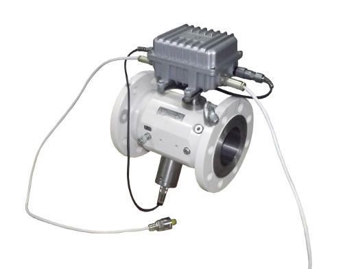
More products on this category
Services List
-
Reference Turbine Gas Meters EFS-T Reference Turbine Gas Meters EFS-T are intended for installation on reference calibration rigs for calibration and verification of gas meters of any type with air as operating environment.
Go to Product Page Reference Turbine Gas Meters EFS-T -
Reference Rotary Gas Meters EFS-R Reference Rotary Gas Meters EFS-R are intended for installation on reference calibration rigs for calibration and verification of gas meters of any type with air as operating environment.
Go to Product Page Reference Rotary Gas Meters EFS-R -
Energoflow GFA-202 Energoflow GFA-202 Flow meters can be used as part of metering units of gas distribution points, industrial enterprises and communal service installation.
Go to Product Page Energoflow GFA-202 -
Energoflow GFE-211, GFE-212 Ultrasonic gas flow meters Energoflow GFE-211 and GFE-212 are a brilliant example of genial engineering for achieving optimal solution for gas flow measurement in large pipes and in cases where installation of inline meters is technically or commercial not viable.
Go to Product Page Energoflow GFE-211, GFE-212 -
Energoflow GFE-201, GFE-202 Energoflow GFE-202 and GFE-201 are state-of-art ultrasonic gas flow meters designed for accurate and reliable measurement of flow velocity, volumetric flow rate and volume of gaseous substances (gases) transported through pipelines in the forward or reverse direction.
Go to Product Page Energoflow GFE-201, GFE-202 -
Flow Metering Complexes for Custody Transfer of Natural Gas The complex can be used for reliable measurement of volumetric data of various gaseous media for custody transfer applications,
Go to Product Page Flow Metering Complexes for Custody Transfer of Natural Gas -
Flow Meters for High Pressure Energoflow GF-201H, GF-202H ultrasonic gas flow meters are flanged section type flow meters specially designed for measuring flow velocity, volumetric flow rate and volume of gaseous substances (gases) transported through pipelines in the forward or reverse direction at high pressure (up-to 16 Mpa),
Go to Product Page Flow Meters for High Pressure -
4-channel Flow Meters for Applications Requiring Enhanced Accuracy Four-channel ultrasonic gas flow meter Energoflow GF- 404 is specially designed for applications where very high accuracy is required, e.g. for custody transfer measurement of natural gas.
Go to Product Page 4-channel Flow Meters for Applications Requiring Enhanced Accuracy

